DD Engineering DD Engineering Trenchless
IT EN

Civil engineering practice

We install pipelines without opening the ground

DD Engineering designs and calculates trenchless crossings: gas, water, fibre, power and sewer lines pass beneath rivers, roads and railways without a trench being opened. We run the numbers before the rig goes into the ground, and we stay on site until the pipe is in place.

  • Detailed design and calculation reports for HDD, microtunnelling and tunnelling
  • In-house software for pullback force, bend radii and downhole pressures
  • Mobile laboratory and GPR: testing on site, not remotely
Horizontal directional drilling rig on station: drill string in the hole, mud containment pit and control cabin HDD · Microtunnelling · GPR

The practice

The figures that define us

100+

Projects completed

Design, site supervision, verification

7years

In trenchless engineering

HDD, microtunnelling, pipe jacking

6

Application sectors

Gas, water, fibre, power, sewer, environmental

1

In-house software

H-DD engineering

Capabilities

Eight disciplines, one point of contact

From ground characterisation to the installed pipeline, without going through three separate suppliers.

HDD & Trenchless

Bore profile, allowable bend radii, pullback forces and stresses on the pipe.

Profile · Pullback

Geotechnical calculation

Ground characterisation, borehole stability, settlement and hydraulic fracture.

Stability · Frac-out

Survey and investigation

High-precision topography, RTK GPS, georeferenced as-built deliverables.

RTK GPS · As-built

Drilling fluid laboratory

Rheology, density and fluid loss of bentonite muds to API RP 13B-1.

Rheology · API

Ground Penetrating Radar

Buried utility mapping before drilling starts: pipes, cables, anomalies.

Utilities

FEM analysis

Soil-structure interaction modelling for critical crossings.

Soil-structure

Operating parameters

Prediction of thrust, torque and flow rates to size the rig and the site.

Thrust · Flow

Pipe stresses

Combined stress checks during installation and in service, against material limits.

Stress · Limits

In-house software

H-DD engineering

One program to design a horizontal directional drilling crossing from start to finish. We wrote it ourselves, around the problems we meet on site: that is why it outputs the drawings the report needs directly, not tables to be laid out again.

01

Bore profile

Straight-arc-straight geometry with checks on minimum radii and on cover over the obstacle.

02

Pullback forces

Weight, friction, fluid drag and capstan amplification through the bends, against rig limits.

03

Hydraulic fracture

Maximum allowable pressure compared with the pressure needed to keep circulation.

04

Stresses on the pipe

Combined tension, bending and external pressure, checked against material limits.

05

Drilling fluids

Flow rates, annular velocity and volumes, consistent with the laboratory data.

06

Drawings

Dimensioned diagrams ready for the report, with nothing to reformat.

Horizontal directional drilling

The profile is settled before the rig enters the ground

Entry angle, bend radii, cover over the obstacle and exit angle are bound to one another: change one and every other changes with it.

Longitudinal profile of a horizontal directional drilling crossing The bore descends at 22 degrees, runs tangent through a 220-radius arc into the horizontal section beneath the riverbed, and rises through a 300-radius arc to an exit inclined at 16 degrees. COVER ENTRY 22°EXIT 16°R 220R 300
Entry angle
22°
Entry arc
R 220
Exit arc
R 300
Exit angle
16°

Three-dimensional view

The bore within the thickness of the ground

The same profile, seen in three dimensions between the strata it crosses. The vertical lines are the depths of cover along the axis: this is the reading that shows where the bore comes too close to the surface.

Bore path Ground level Strata crossed

What we deliver

The design drawings

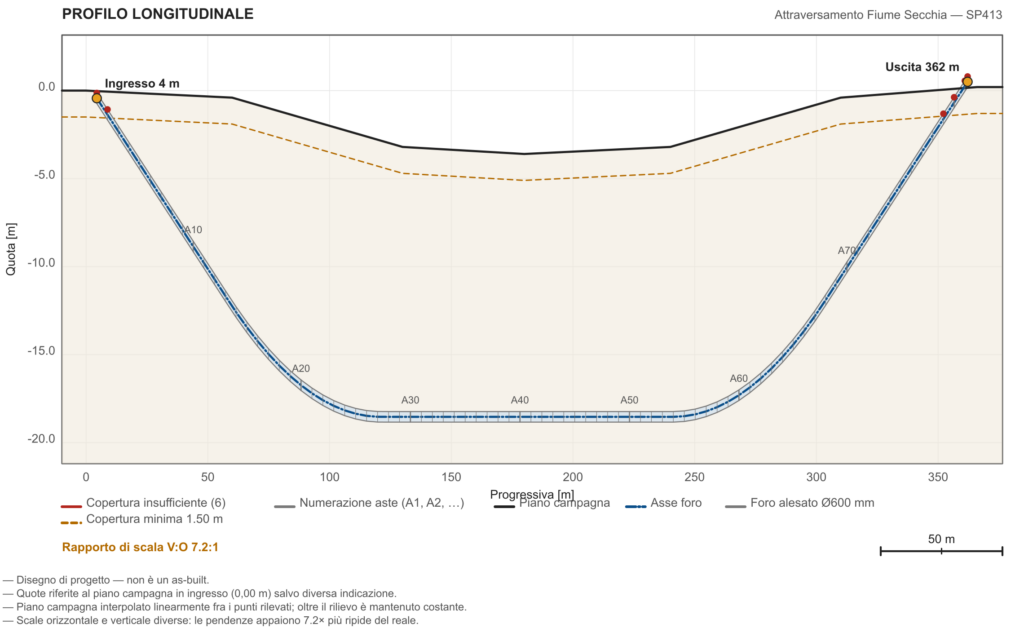
Longitudinal profile of an HDD crossing calculated with H-DD engineering
Dimensioned longitudinal profile
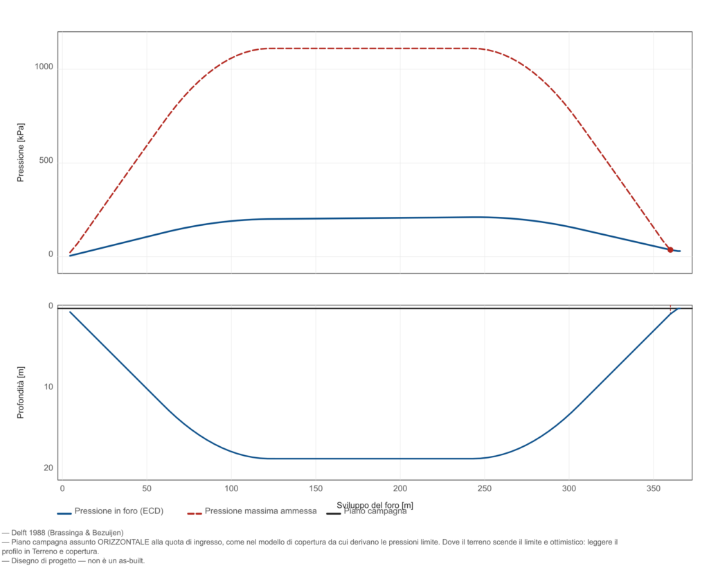
Diagram of downhole pressure compared with the hydraulic fracture limit of the ground
Hydraulic fracture check
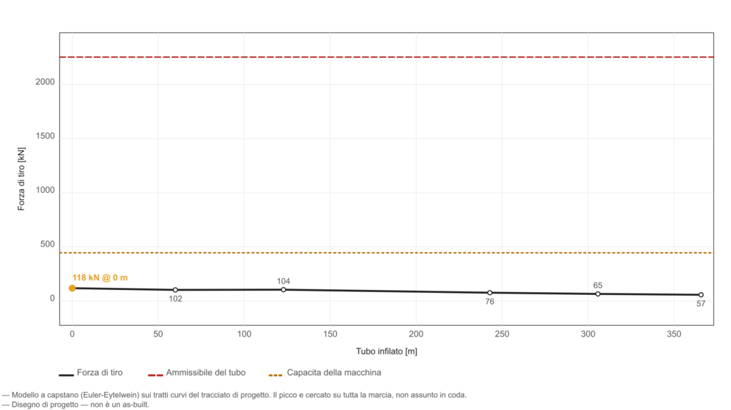
Pullback force curve with the limits of the pipe and of the rig
Pullback force and limits

Design services

Trenchless solutions, engineered to the case
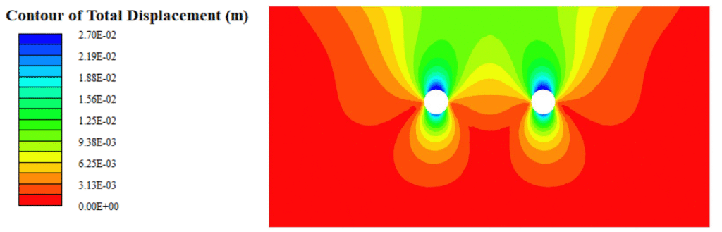
Contour of total displacement induced by the excavation of twin tunnels, in metres

Settlement analysis

Settlement trough, volume loss and damage assessment for buildings at the surface.
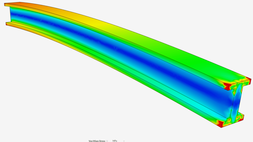
Finite element analysis: Von Mises stress distribution on a beam in bending, in MPa

Structural and FEM analysis

Combined stresses on pipes and interfering structures, checked against material limits.

Design longitudinal profile of a horizontal directional drilling crossing, with entry and exit points dimensioned

Detailed design

Dimensioned drawings and complete documentation for the permitting process.

Fractured basalt rock mass, of the kind that drives the choice of excavation technology

Ground advice

Choice of technology and materials driven by the lithology to be crossed.

In-house laboratory

The fluid is tuned to the ground, not to a catalogue

The mobile laboratory follows the drill on site. Rheology, density and fluid loss are measured on the mud actually in circulation: if the ground changes, the mix changes within the hour.

Pouring drilling mud into the test cell for on-site checking
Sampling the mud for testing
Rotational viscometerYield point, plastic viscosity, gel strengthAPI RP 13B-1
Filter pressLow-pressure fluid loss and filter cakeAPI RP 13B-1
Mud balanceDensity of the fluid in circulationAPI RP 13B-1
Marsh funnelApparent viscosity at the boreholeAPI RP 13B-1
Sand content kitSand content and recycling efficiencyAPI RP 13B-2
Test sievesParticle size of the ground being crossedUNI EN ISO 17892-4

Subsurface diagnostics

What the survey does not tell you

The obstructions that stop a job are almost never on the drawings. Ground penetrating radar finds them before the cutterhead does.

Radargram: the reflection hyperbolas locate three buried utilities at different depths
Radargram acquired in the field
Flanged joint on a steel pipeline, of the kind installed in a crossing
Flanged steel pipeline

Survey and investigation

The alignment is designed on a survey

Not on a cadastral map. We deliver georeferenced as-builts that the client loads straight into their own GIS.

RTK GPS

Centimetre accuracy on entry, exit and the axis of the alignment.

Investigation

Boreholes and testing to characterise the units being crossed.

As-built

Georeferenced deliverables ready for GIS.

GNSS receiver on a survey pole recording the alignment, with earthmoving plant working behind
GNSS survey of the alignment
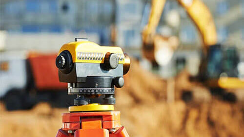
Surveyor at the instrument during the alignment survey
Setting out the entry and exit points

Types of work

How we work, in three scenarios

Scenarios representative of the work we follow, with typical parameters and controls. Project references are available on request.

Pipeline pullback: sidebooms lined up along the right of way lift the string during the pullRiver

Gas pipeline beneath a riverbed

Technology
HDD
Diameter
DN 400
Length
385 m
Cover
6.5 m

Constraint. Downhole pressure close to the fracture limit. Profile lowered by 1.8 m.
Outcome. Pullback 412 kN against 480 calculated, a 14% margin.

Cutaway of a microtunnelling machine: cutterhead, jacking cylinders and spoil removalRoad

Sewer beneath an urban arterial road

Technology
Microtunnelling
Diameter
DN 1000
Length
145 m
Cover
4.2 m

Constraint. Boulders not picked up by the boreholes. Additional GPR survey and the cutterhead revised.
Outcome. Settlement 4 mm against the 10 mm allowed.

Drilling station with the drill string in the hole, containment sheeting and mud collection pitRail

Cable duct beneath a line in service

Technology
Pipe jacking
Diameter
DN 800
Length
62 m
Cover
3.8 m

Constraint. Line in service, 5 mm settlement allowed. Continuous monitoring with a 3 mm trigger.
Outcome. Maximum settlement 2.3 mm.

About us

Who signs the calculations

A team of engineers specialised in underground engineering, based in Carpi and working throughout Italy.

Mohamed Daba

Civil engineer — Trenchless specialist

“I have worked on crossings in demanding urban, industrial and environmental settings. The key is to know the ground thoroughly and to anticipate every variable before it becomes a problem.”

Diego Diambri

Senior trenchless manager

“I look after bentonite fluid monitoring and real-time support to the sites. The in-house laboratory lets us react at once when something changes.”

Four foundations

How we are set up

Engineering expertise, mobile laboratory, in-house design software, GPR and electromagnetic detection. All of it in house, with no technical subcontracting.

Proven experience

Seven years across HDD, microtunnelling, pipe jacking and tunnelling.

Our own technology

Calculation software, FEM and GPR diagnostics under one roof.

In-house laboratory

Fluid testing on site, not two hundred kilometres away.

Low impact

No open-cut excavation: no closures and no reinstatement.

Contact

Tell us about your crossing

Send us the alignment, the diameter and what you know about the ground. We reply within 24 working hours.

Certified e-mailddengineering@pec.it
Office

Corso Sandro Cabassi, 46
41012 Carpi (MO), Italy

Hours

Mon–Fri 8:30–18:00

DD Engineering S.r.l.
VAT and tax code 04202210367 · ATECO 71.12.10 · 71.12.20
Services · Software · Projects · About us · Laboratory
© 2026 — All rights reserved